
Study of Differentiator and Integrator using Operational Amplifier 
Procedure
Experiment
- Integrator using OpAmp
- Connect the components as mentioned below: L1-L7 or L1-L3, L3-L7, L4-L5, L11-L8, L12-L6, L8-L9, L4-L10.(For eg. click on 1 and then drag to 3 and so on.)
- Click on 'Check Connection' button to check the connections.
- If connected wrong click on 'Delete all connection' button to erase all the connections.
- Set the resistance(R) and the capacitance (C) (Intially set R=10 kΩ and C=0.1 µF).
- Click on 'ON' button to start th experiment.
- Click on 'Square Wave' button to generate input waveform.
- Click on 'Oscilloscope' button to get the output waveform.
- Vary the Amplitude, Frequency, volt/div using the controllers.
- Click on "Dual" button to observe both the waveform.
- Channel 1 shows the input square waveform, Channel 2 shows the output waveform.
- Repeat the experiment by applying 'Sine wave' as input.
- Click on 'Sine Wave' button to generate input waveform.
- Click on 'Oscilloscope' button to get the output waveform.
- Vary the Amplitude, Frequency, volt/div using the controllers.
- Click on "Dual" button to observe both the waveform.
- Channel 1 shows the input sine waveform, Channel 2 shows the output waveform.
- Note : Sometimes due to page load or cache, the graph may not come exact at one click. So it is better to double click on the channel-1 function/ channel-2 function/ dual function/ ground function to get the respective signals.
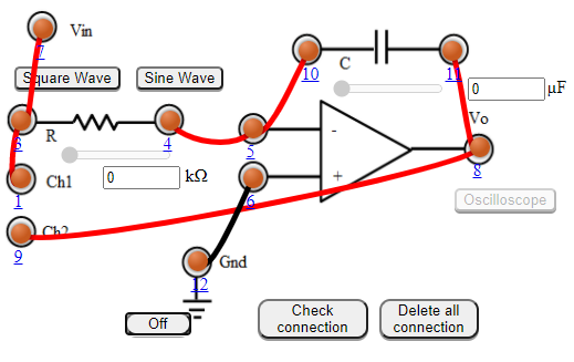
Figure:1
- Differentiator using opamp
- Connect the components as mentioned below: L1-L7 or L1-L3, L3-L7, L4-L5, L11-L8, L12-L6, L8-L9, L4-L10.(For eg. click on 1 and then drag to 3 and so on.)
- Click on 'Check Connection' button to check the connections.
- If connected wrong click on 'Delete all connection' button to erase all the connections.
- Set the resistance(R) and the capacitance (C) (Intially set R=1 kΩ and C=0.1 µF).
- Click on 'ON' button to start th experiment.
- Click on 'Square Wave' button to generate input waveform.
- Click on 'Oscilloscope' button to get the output waveform.
- Vary the Amplitude, Frequency, volt/div using the controllers.
- Click on "Dual" button to observe both the waveform.
- Channel 1 shows the input square waveform, Channel 2 shows the output waveform.
- Repeat the experiment by applying 'Sine wave' as input.
- Click on 'Sine Wave' button to generate input waveform.
- Click on 'Oscilloscope' button to get the output waveform.
- Vary the Amplitude, Frequency, volt/div using the controllers.
- Click on "Dual" button to observe both the waveform.
- Channel 1 shows the input sine waveform, Channel 2 shows the output waveform.
- Note : Sometimes due to page load or cache, the graph may not come exact at one click. So it is better to double click on the channel-1 function/ channel-2 function/ dual function/ ground function to get the respective signals.
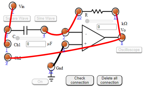
Figure: 2