
RC Frequency Response 
Procedure
Frequency Response of RC Low Pass Filter
- Set Load Resistance(RL)=10 KΩ.
- Set Load Capacitor(CL)=0.01nF.
- The source voltage (Vin) is set to 10V.
- Keeping source voltage constant, vary the frequency from 50 Hz in regular steps.
- Click on "Add to Table" button to add the readings to the table.
- Vary the Frequency by keeping the load resistances and load capacitance constant.
- Select "Plot" button to plot the frequency graph or the phase graph of the RC frequency, Frequency(Hz) along X-axis and Magnitude(dB) along Y-axis.
- Click on "Clear" button to take another set of readings.
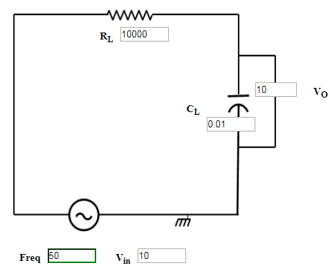
Figure:1
Frequency Response of RC High Pass Filter
- Set Load Resistance(RL)=10 KΩ.
- Set Load Capacitor(CL)=1.91nF.
- The source voltage (Vin) is set to 10V.
- Keeping source voltage constant, vary the frequency from 50 Hz in regular steps.
- Click on "Add to Table" button to add the readings to the table.
- Vary the Frequency by keeping the load resistances and load capacitance constant.
- Select "Plot" button to plot the frequency graph or the phase graph of the RC frequency, Frequency(Hz) along X-axis and Magnitude(dB) along Y-axis.
- Click on "Clear" button to take another set of readings.
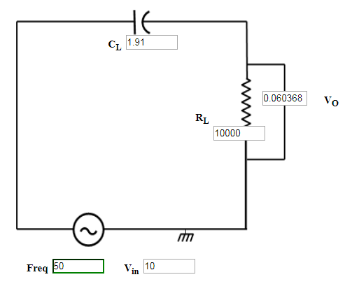
Figure:2