
VI Characteristics of a Diode 
Procedure
Forward Bias-Si Diode
- Set DC voltage to 0.2 V .
- Select the diode.
- Set the resistor.
- Voltmeter is placed parallel to Silicon diode and ammeter series with resistor.
- The positive side of battery to the P side(anode) and the negative of battery to the N side(cathode) of the diode.
- Now vary the voltage upto 5V and note the Voltmeter and Ammeter reading for particular DC voltage .
- Take the readings and note Voltmeter reading across Silicon diode and Ammeter reading.
- Plot the V-I graph and observe the change.
- Calculate the dynamic resistance of the diode. rd=ΔV/ΔI
- Therefore from the graph we see that the diode starts conducting when the forward bias voltage exceeds around 0.6 volts (for Si diode). This voltage is called cut-in voltage.
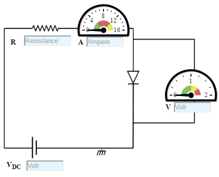
Figure:1
Reverse Bias-Si Diode
- Set DC voltage to 0.2 V .
- Select the diode.
- Set the resistor.
- Voltmeter is placed parallel to Silicon diode and ammeter series with resistor.
- The positive terminal of battery is connected to the N side(cathode) and the negative terminal of battery is connected to the P side(anode) of a diode.
- Now vary the voltage upto 30V and note the Voltmeter and Ammeter reading for DC voltage .
- Take the readings and note Voltmeter reading across Silicon diode and Ammeter reading.
- Plot the V-I graph and observe the change.
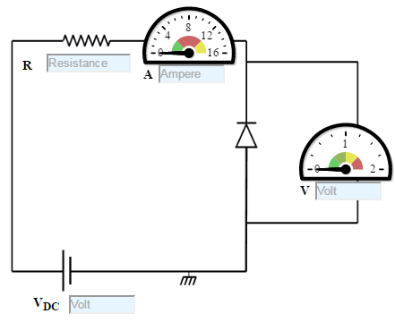
Figure: 2
Forward Bias-Ge Diode
- Set DC voltage to 0.2 V .
- Use the resistor of 1K ohms and a Germanium diode.
- Voltmeter is placed parallel to Germanium diode and ammeter series with resistor.
- The positive terminal of battery is connected to the P side(anode) and the negative terminal of battery is connected to the N side(cathode) of the diode.
- Now vary the voltage upto 30V and note the Voltmeter and Ammeter reading for particular DC voltage .
- Take the readings and note Voltmeter reading across Germanium diode and Ammeter reading.
- Plot the V-I graph and observe the change.
- Therefore from the graph we see that the diode starts conducting when the forward bias voltage exceeds around 0.3 volts (for Ge diode). This voltage is called cut-in voltage.
Figure: 3
Reverse Bias-Ge Diode
- Set DC voltage to 0.2 V .
- Use the resistor of 1K ohms and a Germanium diode.
- Voltmeter is placed parallel to Germanium diode and ammeter series with resistor.
- The positive terminal of battery is connected to the N side(cathode) and the negative terminal of battery is connected to the P side(anode) of a diode.
- Now vary the voltage upto 30V and note the Voltmeter and Ammeter reading for DC voltage .
- Take the readings and note Voltmeter reading across Silicon diode and Ammeter reading.
- Plot the V-I graph and observe the change.
Figure: 4