
Studies on BJT CE Amplifier 
Procedure
Experiment
- The source voltage (VS) is set to 50mV at 1 KHz frequency.
- Keeping source voltage constant, vary the frequency from 50 Hz in regular steps.
- Set Source Resistance(RS)=100Ω.
- Set Collector Resistance(RC)=4000Ω, Set Emitter Resistance(RE)=1000Ω, Set Load Resistance(RL)=2000Ω.
- Set Base Resistance1(RB1)=47 KΩ, Set Base Resistance2(RB2)=10KΩ.
- Set Coupling Capacitor1(CC1)=10μF, Set Coupling Capacitor2(CC2) =10μF, Set Bypass Capacitance(CE)=10μF.
- Click on "Add to Table" button to add the readings to the table.
- Vary the Frequency by keeping the resistances constant.
- Click on "Plot" button to plot the Magnitude graph of the CE Amplifier, Frequency(Hz) along X-axis and Magnitude(dB) along Y-axis.
- Click on "Clear" button to take another set of readings.
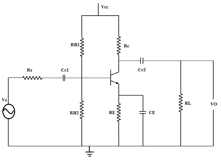
Figure:1